|
|
|
This video shows tips on soldering work for engineers. It mainly shows
the steps for surface mounting that have been more recently popular. We
hope this video will be useful for reference.
Thread solder typically has the following characteristics.
* Only flows when melted at high temperatures.
* Maintains sufficient viscosity to form solder balls when melted.
* Viscosity increases with the passage of time, due to evaporation of flux.
Heat up the joint quickly with the tip of the iron and apply solder. Remove
the iron as soon as solder flows into the joint. A slightly thicker type
of iron with a tapered chisel tip is recommended, as a thick blade enables
greater heat storage, and the slanted end is easier to fit into small gaps
between pins and/or electrodes. Slanted cut tip allows easier access to
the narrower pitch between pins and/or electrodes. This can also be used
for surface mounting soldering.
It can heat up more quickly on the wider flat surface of its blade rather
than the pinpoint of its tip end. Adjust contact area according to the
conditions of the parts and the land. For larger lands or GNDs for example,
it’s quicker for heating wider areas. For parts removal you can increase
the contact area by angling the tip of the iron.
We use a ceramic type iron with a temperature control (these are available
at low cost. Do not expose circuit boards to unnecessary thermal stress.
Prolonged exposure to heat can cause lands to peel off depending on the
manufacturer and adhesive used.
Parts positioning is one of the most important aspects of soldering. Tidy
arrangement of parts on the substrate makes the following soldering work
easier. Supporting the iron / tweezers hand firmly with your elbow or wrist
will allow you to make more stable soldering work.
Soldering work is extremely important for high frequency circuits. Special
attention should be paid to the amount of solder to be applied and the
shape of the solder as it may influence the characteristics of the circuit
board.
|
|
|
|
 |
IC chip (DIP type)
* Mounting method
Use a thick solder tip for DIP type IC, as they diffuse heat rapidly. If
the iron has insufficient thermal capacity, solder will not flow over the
substrate smoothly, At first, place the iron to the electrode of the component
through pinholes and raise the temperature, and then apply solder. Heat
parts that lose heat quickly (e.g., GND) for slightly longer.
|
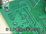
Soldering DIP parts |
|
|
|
|
1608 (0603) size resistor
* Mounting method
Solder to one side of the land first. Fix the resistor in place while melting
solder. Solder the other electrode. It’s finished. If the finish is not
satisfactory, heat both electrodes again, and re-melt the solder. Afterwards,
withdraw the iron, and the resistor will fall into place on the land by
surface tension, and the solder will flow and become stable. If there is
too much solder, remove it with the iron.
|
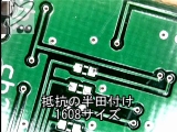
Soldering resistor 1608 size |
|
* Desoldering method
Hold the iron diagonally and heat both electrodes. If there is not enough
solder, add more. When the solder has melted, remove it by using tweezers
or by moving the resistor with the iron. The key is to apply more solder
at this point. Do not apply force before the solder melts. |
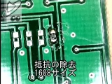
Removal of resistor 1608 size |
|
* Desoldering
Remove the solder with the desoldering wick as necessary. Heat sufficiently
to prevent solder from sticking to the land. Wipe off the solder without
applying too much force, as the land may peel off. |
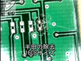
Removal of resistor 1608 size |
|
|
|
|
1005 (0402) size resistor
* Mounting method
Basically soldering method is similar to that of the 1608 size, but be careful as it is slightly smaller and lighter.
|
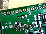
Soldering resistor 1005 size |
|
* Desoldering method
It is easier to heat both electrodes because it is smaller than the1608
size.
|
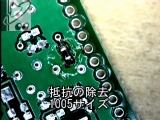
Removal of resistor 1005 size |
|
* Desoldering
Similar to the method of 1608 size, do not apply too much force.
|
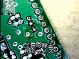
Desoldering Method 1005 size |
|
|
|
|
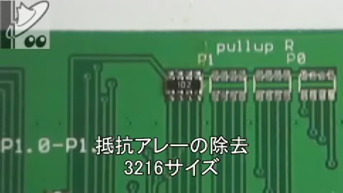
3216 (1206) size resistor array
* Mounting method
First, solder on one side of the land. Fix the resistor array while melting
the solder. Apply solder on the other side.
If it’s out of position, melt the solder on both sides of pins and reposition by utilizing surface tension.
|
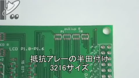
Soldering resistor array 3216 size |
|
* Desoldering Part1
Remove it by heating both sides of the pins.
|
Desoldering Part1 3216 size |
|
* Desoldering Part2
Clean the land after removing the resistor array. The key is to clean the
land while melting the solder.
Do not move the desoldering wick with force. Desolder gently so as not
to peel off the land by heat.
|
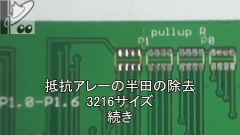
Desoldering Part2 3216 size |
|
|
|
|
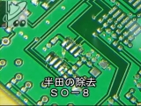
Half-pitched SOP package IC (8Pin)
* Mounting method
SOP packages have wider pin intervals between the parts used for surface
mounting and are easy to solder. First, solder on one land for positioning.
Hold the IC with tweezers and melt solder. Position each pin separately
in the center of the land then remove the iron. Positioning of the parts
is now finished. Solder the rest of the pins in sequence. Heat up the land
for longer before soldering, as it loses heat quickly (like the GND).
|
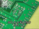
SOP soldering SO-8 |
|
* Desoldering Part1
Remove the IC by adding solder on both sides of the pins and heating up alternately.
You can remove it with either one or two irons.
|
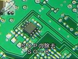
SOP removal SO-8 |
|
* Desoldering Part2
Clean the land after removing the IC. The key is to clean the land while
the solder is melted. Do not move the desoldering wick with force.
|
SOP removal SO-8 |
|
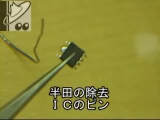
* Desoldering IC pin
Remove extra solder on IC pin. Clean the land with desoldering wick or
by applying iron to the pins from top to bottom.
|
Desoldering IC pin |
|
|
|
|
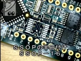
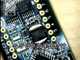
SSOP package IC 0.65 mm pitch (16pin)
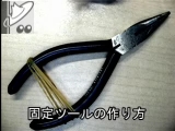
* Fixing tool
Work with a fixing tool. For pressing parts; attach a tooth pick to the
tip of radio pliers.
In this video, just the tip of a tooth pick is used but it is ok to use
as it is.
|
How to make a fixing tool. |
|
* Mounting method Part1
IC is positioned using the fixing tool for soldering. For SSOP with narrow
pitches, the iron should be temporarily applied and then removed. The video
only covers to the end of the soldering.
|
Soldering SSOP SSOP-16 Part1 |
|
* Mounting method Part2
The applied solder is removed. Use the desoldering wick to remove the solder.
For finishing purposes, a desoldering wick with some solder attached provides
a better finish than a new desoldering wick.
|
Soldering SSOP SSOP-16 Part2 |
|
* Desoldering method
Apply solder to the pins on both sides, then remove by heating them alternately
like SOP.
Heat iron sufficiently in order to melt solder on both sides.
|
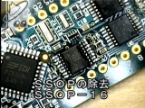
Desoldering of SSOP SSOP-16 |
|
* Desoldering of IC pin
Apply and remove solder like SOP. Clean up like SSOP.
|
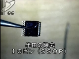
Desoldering IC pin (SSOP) |
|
|
|
|
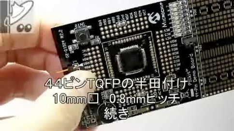
TQFP package IC 0.8 mm pitch (44 pin)
* Mounting method Part1
Use the fixing tool for TQFP. If the iron’s tip moves the IC, use a heavier
tool to hold in position, or attach half portion of the IC to the substrate
with tape, to temporarily fix the pins that stick out. Apply solder to
each pin after fixing it temporarily.
|
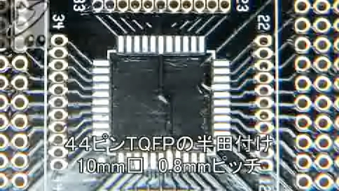
Soldering of TQFP (44 pin)
10 mm square 0.8 mm pitch Part1 |
|
* Mounting method Part2 (Remove solder)
The following method can be used in the case of wide pitches, or alternatively use a desoldering wick.
Hold the substrate diagonally downward, apply the iron to the pins from
top to bottom, and remove the excess solder. A thick iron is recommended.
|
Soldering of TQFP (44 pin)
10 mm square 0.8 mm pitch Part2 |
|
* Mounting method Part3
・実装方法 続き
Use a desoldering wick to remove any remaining excess solder after using above method.
|
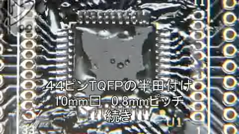
Soldering of TQFP (44 pin)
10 mm square 0.8 mm pitch Part3 |
|
* Desoldering method
Apply solder to each pin and heat alternately by using two irons.
Melting all the solder simultaneously requires a sufficiently hot iron.
|
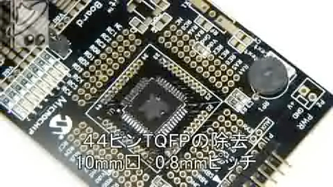
Desoldering of TQFP (44 pin)
10 mm square 0.8 mm pitch Part1 |
|
* Desoldering
Remove solder by heating the desoldering wick in the same manner as SOP. Desolder gently so as not to peel off the land. Move it lengthwise on the land to prevent short-circuits and peeling.
|
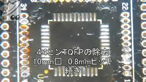
Desoldering of TQFP (44 pin)
10 mm square 0.8 mm pitch Part2 |
|
|
|
|
QFN package IC 0.65 mm pitch (44 pin)
* Mounting method Part1
Soldering a package without pins. Soldering can be achieved with an iron;
although it depends on the land shape. The processes from positioning package
to temporary soldering are the same as for the other IC. You can solder
cleanly by using a thick iron.
|
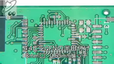
Soldering QFN (44 pin)
8 mm square 0.65 mm pitch Part1 |
|
* Mounting method Part2
Holding the substrate vertically remove excessive solder by applying the
heated iron from top to bottom of the pins. In most cases, using the desoldering
wick for excess solder removal is not required as it rarely causes short-circuits
compared to TQFP.
|
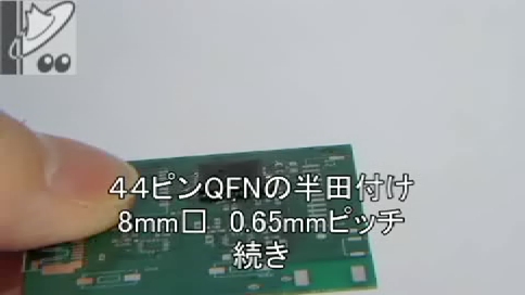
Soldering QFN (44 pin)
8 mm square 0.65 mm pitch Part2 |
|
* Mounting method Part3
It shows after soldering.
|
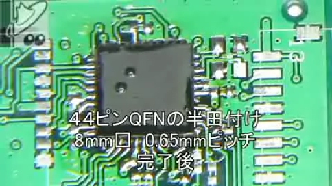
After soldering QFN (44 pin)
8 mm square 0.65 mm pitch |
|
|
|
|
Female header socket (2.54 mm pitch)
* Mounting method
Hold the substrate up, firmly set the female header socket on it, and join
them temporarily at two points. When the substrate and pins are sufficiently
heated apply solder to pins sequentially. See the video for details.
|
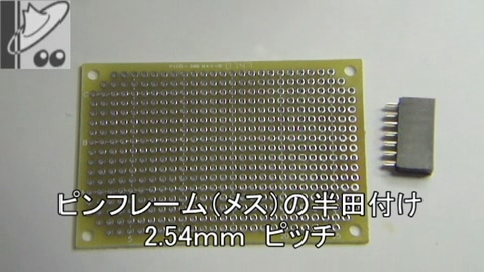
Soldering Female header |
|
* Desoldering Part1
Make a fixing tool with pliers, radio pliers or similar. Use heavier tool
to stabilize it. Pinch the female header socket with the fixing tool from
the bottom and apply solder. After that, melt the solder of all the pins,
pick the substrate up and pull out the connectors. You can also use a vice.
|
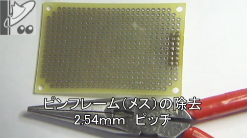
Desoldering of Female header Part1 |
|
* Desoldering Part2
Remove the solder on the land after the female header socket is taken off.
Melt the solder to absorb it with the desoldering wick.
|
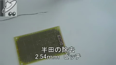
Desoldering of Female header Part2 |
|
* Desoldering of pins
Remove the solder on the female header socket too. Using a thick iron-tip, melt and remove the solder quickly. Apply the iron from the bottom with careful attention.
|
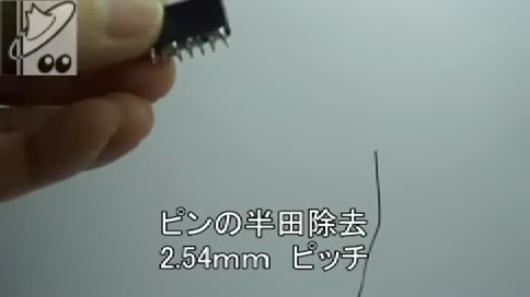
Desoldering of pins |
|
|
|
|
Soldering cable
Peel off the coating from the cable with the wire stripper, solder, and
attach it on the substrate. Carefully fix the cable on the substrate and
solder it.
|
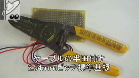
Soldering cable |
|
|
|